Skip to content
AI GPU Data Center

Infrastructure

The physical layer of AI.

AI GPU Data Center is developing dedicated GPU infrastructure as an integrated physical and operational system — hardware, fabric, power, cooling, security and operations planned together rather than assembled after the fact.

Modular compute architecture diagramPower enters through structural pathways into Unit 01, the 1MW planned first-phase deployment, with cooling above and network below the compute racks. A dashed expansion grid to the right represents the phased pathway towards 5MW, connected to a faint global network.POWERCOOLINGNETWORKUNIT 01 · 1MWEXPANSION · TOWARDS 5MW
  • Power — grid supply enters the unit
  • Cooling — thermal capacity above the racks
  • Network — interconnect and transit below the racks
  • Unit 01 — 1MW planned first-phase capacity
  • Expansion — phased pathway towards 5MW

Design principle

AI GPU Data Center's infrastructure model treats compute as an integrated physical and operational system. Hardware selection remains configurable according to workload requirements, with NVIDIA B300 systems forming the planned initial build-out.

Architecture layers

Nine layers, one operating envelope.

Layer 01

GPU systems

High-density accelerated compute forming the core of each deployment. NVIDIA B300 systems are the planned initial architecture; alternative configurations remain available according to client requirements.

Planned specification

Design intent, stated plainly.

The table below records current design intent for the first phase. It is not a product datasheet and contains no performance, uptime or availability claims.

Compute

Initial GPU architecture
NVIDIA B300 systems (planned initial build-out)
Alternative configurations
Selected according to client workload and commercial requirements
Access model
Dedicated bare-metal — no shared tenancy on client infrastructure
Host compute and memory
Sized to keep accelerators supplied for the target workload

Fabric and storage

GPU interconnect
High-speed low-latency fabric planned for distributed multi-node training
Cluster networking
Segmented client networking with controlled external connectivity
Storage
Throughput-oriented tiers designed around dataset size and checkpoint behaviour

Facility

First-phase capacity
1MW planned
Expansion pathway
Phased towards 5MW, aligned with contracted demand
Power
Distribution, redundancy and headroom treated as a primary design input
Cooling
Thermal design matched to high-density racks and site conditions

Operations

Monitoring
Power, thermal, fabric and node telemetry for operations and lifecycle planning
Security and access
Physical, logical and administrative controls for data-sensitive workloads
Managed operations
Operation, maintenance and lifecycle activity under an agreed service framework

Unit 01

The first module, as ordered.

Equipment for the first modular deployment has been ordered. The figures below describe what is committed rather than what is intended.
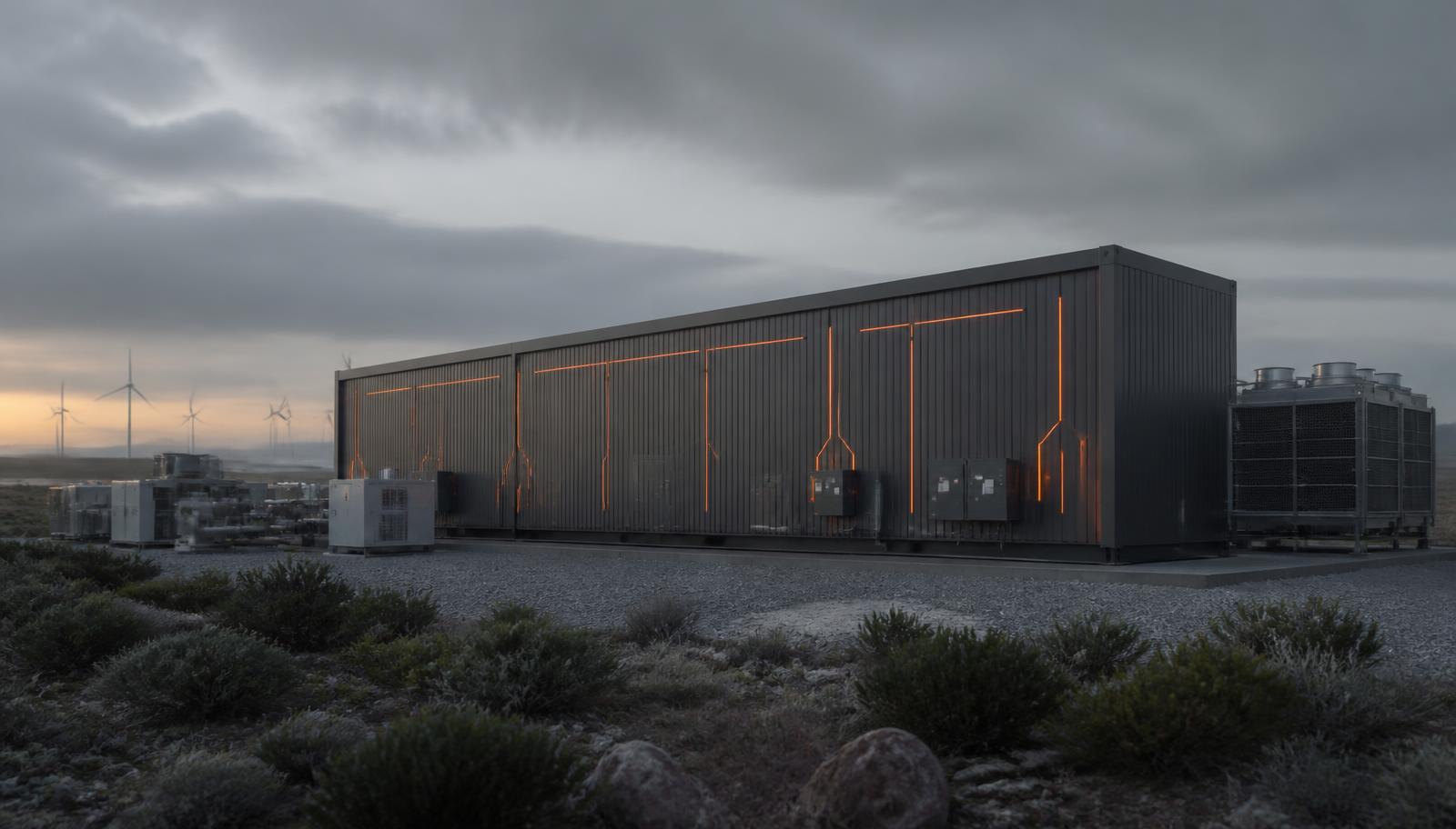
Render of a planned modular data centre unit at dusk, with external cooling plant beside it.
Render of planned infrastructure
Status
Equipment ordered — modular unit, racks, chillers and cooling
Initial compute
8 × Supermicro NVIDIA HGX B300 servers — 64 B300 GPUs
Pre-provisioned capacity
16 servers / 128 GPUs within the same module
Cooling
Rear-door heat exchangers matched to high-density racks
Module cadence
Further modules planned on an approximately quarterly import cycle

Locations and power

Sites chosen where power and data residency line up.

Deployment is modular, so each site is assessed on its own power position. Grid connection, generation, storage and redundancy arrangements are developed per site and published once contracted.

01

Sovereign data requirements

Capacity is placed in jurisdictions where clients need their data and workloads to remain, rather than routed offshore by default.

02

Wind and solar availability

Sites are shortlisted where renewable generation is available locally, so power strategy and site selection are decided together.

03

At least 1MW of green energy

A minimum of 1MW of green energy at the site is a selection criterion for each earmarked location.

Earmarked sites

  • Humansdorp

    South Africa

  • Atlantis

    South Africa

  • Harare

    Zimbabwe

Integrated system

Every layer is a potential constraint.

  1. 01

    Power

    Supply, distribution, redundancy

  2. 02

    Facility

    Cooling, density, physical security

  3. 03

    Compute

    GPU, CPU, memory

  4. 04

    Network

    Interconnect, storage, transit

  5. 05

    Workload

    Training, inference, research

One integrated system — a constraint in any layer becomes a constraint on the workload

Phased capacity development

Built in increments, against contracted demand.

Phase 01

1MW planned initial deployment

Dedicated high-density infrastructure based on NVIDIA B300 systems, subject to final engineering and client requirements.

Expansion

Phased pathway towards 5MW

Additional capacity developed according to client uptake, power availability, technical requirements and contracted offtake.

Future Scale

Repeatable infrastructure growth

A modular operating model designed to support additional capacity and future infrastructure locations as demand develops.